h-Method & p-Method
When modeling a problem using a finite element program, it is very important to check whether the solution has converged. The word convergence is used because the output from the finite element program is converging on a single correct solution. In order to check the convergence, more than one solution to the same problem are required. If the solution is dramatically different from the original solution, then solution of the problem is not converged. However, if the solution does not change much (less than a few percent difference) then solution of the problem is considered converged.
Currently, two types method are used to demonstrate the numerical convergence of the solution :
1). h – method
2). p – method
The h- and p- versions of the finite element method are different ways of adding degrees of freedom (dof) to the model (Figure 1).
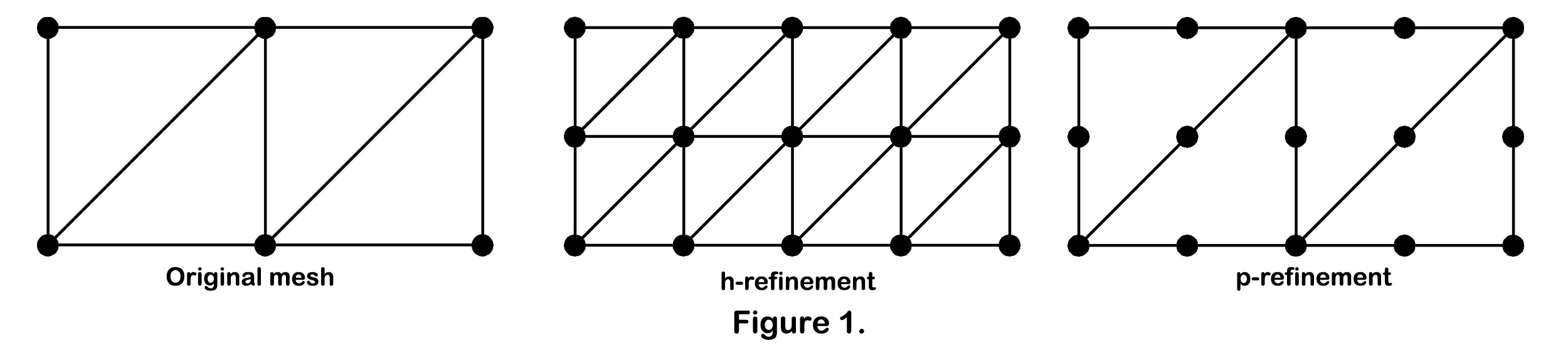
h-method –> The h-method improves results by using a finer mesh of the same type of element. This method refers to decreasing the characteristic length (h) of elements, dividing each existing element into two or more elements without changing the type of elements used.
p-method –> The p-method improves results by using the same mesh but increasing the displacement field accuracy in each element. This method refers to increasing the degree of the highest complete polynomial (p) within an element without changing the number of elements used.
The difference between the two methods lies in how these elements are treated. The h-method uses many simple elements, whereas the p-method uses few complex elements.
H-Method
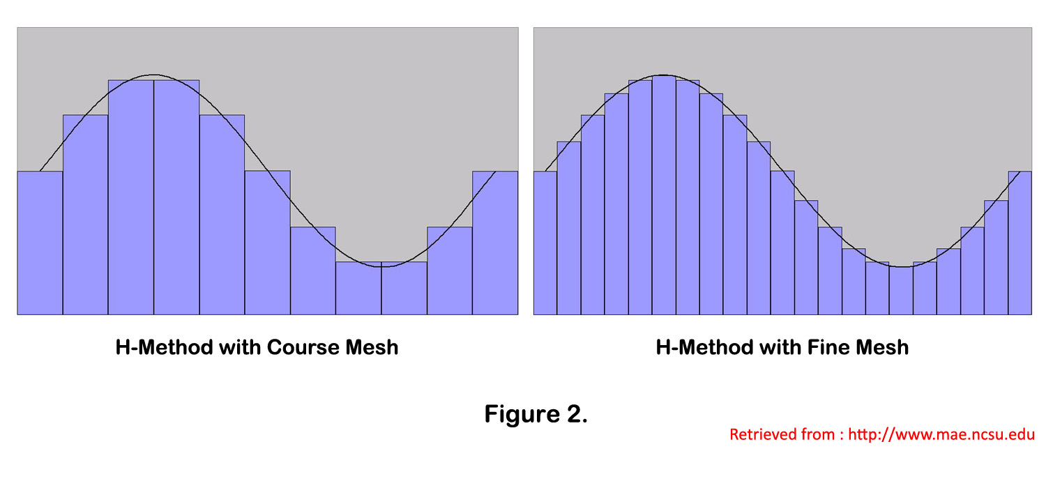
More accurate information is obtained by increasing the number of elements.The name for the h-method is borrowed from mathematics. The variable h is used to specify the step size in numeric integration. If a part is modeled with a very course mesh, then the stress distribution across the part will be very inaccurate. In order to increase the accuracy of the solution, more elements must be added. This means creating a finer mesh. As an initial run, a course mesh is used to model the problem. A solution is obtained. To check this solution, a finer mesh is created. The mesh must always be changed if a more accurate solution is desired. The problem is run again to obtain a second solution. If there is a large difference between the two solutions, then the mesh must be made even finer and then solve the solution again. This process is repeated until the solution is not changing much from run to run.
P-Method
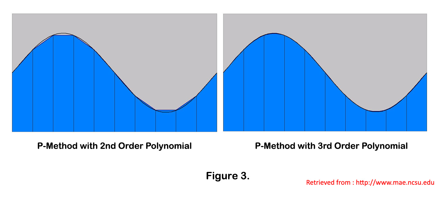
The p in p-method stands for polynomial. Large elements and complex shape functions are used in p-method problems. In order to increase the accuracy of the solution, the complexity of the shape function must be increased. Increasing the polynomial order increases the complexity of the shape function.The mesh does not need to be changed when using the p-method.
As an initial run, the solution might be solved using a first order polynomial shape function. A solution is obtained. To check the solution the problem will be solved again using a more complicated shape function. For the second run, the solution may be solved using a third order polynomial shape function. A second solution is obtained. The output from the two runs is compared.
If there is a large difference between the two solutions, then the solution should be run using a third order polynomial shape function. This process is repeated until the solution is not changing much from run to run.
References :
Good Solid Modeling, Bad FEA by PAUL KUROWSKI
H-Code vs. P-Code : The Facts (Why Mechanica (Pro/ENGINEER Structural Simulation Option) is a better Solution for Design Engineers).
Thank You…..Everyone is Number One
Meshing Methods (ANSYS Meshing)
Meshing is an integral part of the computer-aided engineering simulation process. The mesh influences the accuracy, convergence and speed of the solution. Furthermore, the time it takes to create and mesh a model is often a significant portion of the time it takes to get results from a CAE solution. From easy, automatic meshing to a highly crafted mesh, ANSYS provides the ultimate solution. Once the best design is found, meshing technologies from ANSYS provide the flexibility to produce meshes that range in complexity from pure hex to highly detailed hybrid; a user can put the right mesh in the right place and ensure that a simulation will accurately validate the physical model.
Meshing Process in ANSYS Meshing :

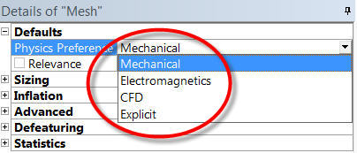
Physics preference in ANSYS Meshing are : Mechanical, Electromagnetics, CFD and Explicit.
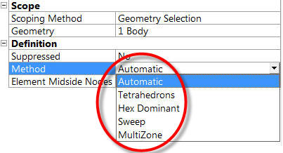
Meshing methods available for 3D bodies : Automatic, Tetrahedrons, MultiZone, Hex Dominant, Sweep, CutCell.
Meshing methods available for 2D bodies : Automatic Method (Quad Dominant), Triangles, Uniform Quad/Tri, Uniform Quad.

Tipe – tipe element di Solidworks Simulation
Ada 5 tipe element di Solidworks Simulation : First order solid tetrahedral elements, Second order solid tetrahedral elements, First order triangular shell elements, Second order triangular shell elements, Beam elements.
Di dalam terminology Solidworks Simulation, First Order Elements mengacu pada Draft Quality Elements, sedangkan Second Order Elements mengacu pada High Quality Elements.
First Order Solid Tetrahedral Elements mempunyai 4 node, masing – masing di corner. Setiap node mempunyai 3 DOF.

Second Order Solid Tetrahedral elements mempunyai 10 node (4 di corner dan 6 di mid-side). Setiap node mempunyai 3 DOF.

Basic FEA Test
Source : http://www.scribd.com/doc/19260249/Basic-FEA-Test
Answer True OR False to the following :
1. The finer the FE mesh on a model, the better the results.
2. A finer mesh gives better accuracy.
3. Geometry should be represented with as much detail as possible.
4. Solids give the best results because they accurately model the geometry.
5. Better (more-expensive) FEA software gives better results than less-expensive packages.
6. Automeshing is better than manual meshing.
7. An automatic-mesh generator reduces meshing to a pushbutton operation.
8. The high accuracy of FEA results comes from the high processing accuracy of the computer.
9. When your FEA software reports no error, the solution will be correct.
10. You do not really need an error estimation. FEA is always accurate enough.
Efek Venturi Pada Bangunan/StrukturTinggi
Akibat perilaku angin yang kompleks pada bangunan/struktur tinggi seperti : vortex shedding, efek venturi, dan perilaku dinamis lainnya, maka uji terowongan angin (wind tunnel) menjadi sesuatu yang sangat penting pada bangunan/struktur tinggi. Untuk memangkas waktu dan biaya, sebelum dilakukan uji terowongan angin sebaiknya bangunan/struktur tinggi dianalisa terlebih dahulu dengan metode dinamika fluida numerik (CFD). Dengan analisa CFD maka kita bisa memperoleh gambaran awal tentang perilaku angin terhadap bangunan/struktur tinggi. Untuk perbandingan antara wind tunnel dan CFD dapat dibaca disini.
Salah satu penyebab kolapsnya 3 cooling tower di Ferrybridge, England adalah karena efek venturi yang timbul di antara cooling tower tidak terlalu mendapatkan perhatian. Gambar 1 memperlihatkan kolapsnya 3 cooling tower di Ferrybridge, England.

Efek venturi menjelaskan bahwa ketika fluida mengalir dalam bagian pipa yang penampangnya kecil dan berada pada ketinggian yang sama, maka kecepatan fluida di daerah tersebut akan semakin besar untuk mempertahankan debit fluida . Analisa CFD akan membantu kita untuk mempelajari fenomena efek venturi pada kelompok bangunan/struktur tinggi. Kali ini saya akan mengambil contoh analisa aliran pada susunan bangunan yang berbentuk silinder.

Pada Gambar 2, dapat kita lihat bahwa terjadi peningkatan kecepatan aliran fluida pada celah kedua buah silinder ( A & B) yang berpengaruh terhadap silinder yang ada di belakangnya (C).
Mesh Consideration in FEA and CFD Analysis

Meshing is still one of the most important tasks for most CAE users. You need make judgements whether the mesh is good enough for your physical problem. Here are the mesh consideration in FEA and CFD analysis. I know there are probably some other good considerations. If you get one, please post it in the comments box below.
1. For simple comparison of different designs, coarse mesh is OK but for accurate stresses, finer mesh is needed.
2. Invest elements at locations of interest (refining the mesh only in the regions of interest). Greater numbers of elements require more compute resource (memory / processing time). Balance the fidelity of the simulation with available resources.
3. Elements distorted from their basic shape can be less accurate. Greater the distortion, the greater the error. Four types of distortion : Aspect ratio (elongation), Angular distortion (skew and taper), Volumetric distortion, Mid node position distortion (higher order elements)

4. When you choose an element type, you are implicitly choosing and accepting the element shape function assumed for that element type. Therefore, check the shape function information before you choose an element type.
Tegangan Maksimum Pada Pelat Berlubang (Elliptical Hole)


Persamaan untuk menghitung tegangan maksimum diberikan oleh :
![]() , dimana K adalah stress concentration factor
, dimana K adalah stress concentration factor
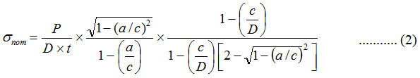
Persamaan untuk menghitung tegangan (σnom) pada plat (finite plate) dengan lubang yang berbentuk elips diberikan oleh persamaan :
FEA User Beware !
(Source : MECHANICA Tutorial, By Roger Toogood, Ph.D., P.Eng)
Users of this (or any other FEA) software should be cautioned that, as in other areas of computer applications, the GIGO (“Garbage In = Garbage Out”) principle applies. Users can easily be misled into blind acceptance of the answers produced by the programs. Do not confuse pretty graphs and pictures with correct modeling practice and accurate results.
A skilled practitioner of FEA must have a considerable amount of knowledge and experience. The current state of sophistication of CAD and FEA software may lead non- wary users to dangerous and/or disastrous conclusions. Users might take note of the fine print that accompanies all FEA software licenses, which usually contains some text along these lines: “The supplier of the software will take no responsibility for the results obtained . . .” and so on. Clearly, the onus is on the user to bear the burden of responsibility for any conclusions that might be reached from the FEA.
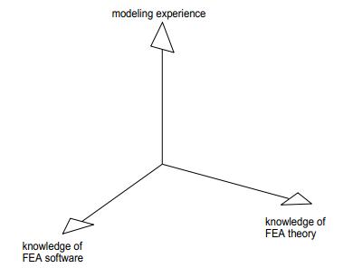
We might plot the situation something like Figure 1. In order to intelligently (and safely) use FEA, it is necessary to acquire some knowledge of the theory behind the method, some facility with the available software, and a great deal of modeling experience.

Behavior of Contact (In ANSYS)
In ANSYS, the contact is generated by pair. For the point-surface contact, the “point” is contact and the “surface” is target. For surface-surface contact, both contact and target are surfaces and they have to be specified which surface is contact and which is target. No matter it’s point-surface contact or surface-surface contact, as soon as they are identified, they are then one pair.One can not exist without the other.
For the surface-surface contact, it is the first step to specify which is contact surface and which is target surface. Normally, convex surface is chosen as contact and concave as target. Also when the size of one body in contact compared to another one is very small and then the large surface is chosen as target. There are several kinds of contact used in ANSYS: frictional, frictionless, rough, bonded, no separation and so on. Contact surface has different types of behavior according to different characteristics of contact.
 Figure. 1

Figure. 2
Investigation Of Air Flow Around Buildings Using Computational Fluid Dynamics Technique
Engineering projects are now demanding design solutions that are beyond standard practise. To meet this challenge the utilization of sophisticated numerical modeling techniques, such as CFD (Computational Fluid Dynamics) being able to provide innovative engineering design solutions. CFD techniques have been applied in predicting wind flow conditions : around a single building, between two parallel buildings , and around multiple building configuration. I would like show some results obtained in numerical solutions using CFD techniques. These results summarized from some literature.
A. Validation of the Computational Fluid Dynamics (CFD) Method for Predicting Wind Flow Around a High-Rise Building (HRB) in an Urban Boundary Layer Condition Condition. (By Abdul Razak Sapian)
This study attempts to validate and justify the realibility of Flovent by investigating the wind flow around a high rise building. The main goal of this paper is to determine if the CFD method can be be used to study wind flow around a high-rise building. The data obtained from the simulation are compared with wind tunnel data.

The size of building was 78 m x 10 m x 50 m. The building was placed inside an overall domain solution size of 318 m x 450m x 240 m high.The position of the building inside the overall domain solution was 120 m from x-plane, 250 m from z-plane, and 0 m from y-plane.
Results of simulation :

Conclusion from this paper :
The results obtained from the simulation show a deviation of less than 15% compared with wind tunnel results.
Shelvam (1992) allowed up to a 7% deviation for the average windward point between his CFD calculation and the experimental data.
In a separate case study, another CFD expert, Shao (1992), accepts a 20% tolerance for a good agreement between his CFD Codes’ Cp results and the experiment data.

