Archive
h-Method & p-Method
When modeling a problem using a finite element program, it is very important to check whether the solution has converged. The word convergence is used because the output from the finite element program is converging on a single correct solution. In order to check the convergence, more than one solution to the same problem are required. If the solution is dramatically different from the original solution, then solution of the problem is not converged. However, if the solution does not change much (less than a few percent difference) then solution of the problem is considered converged.
Currently, two types method are used to demonstrate the numerical convergence of the solution :
1). h – method
2). p – method
The h- and p- versions of the finite element method are different ways of adding degrees of freedom (dof) to the model (Figure 1).

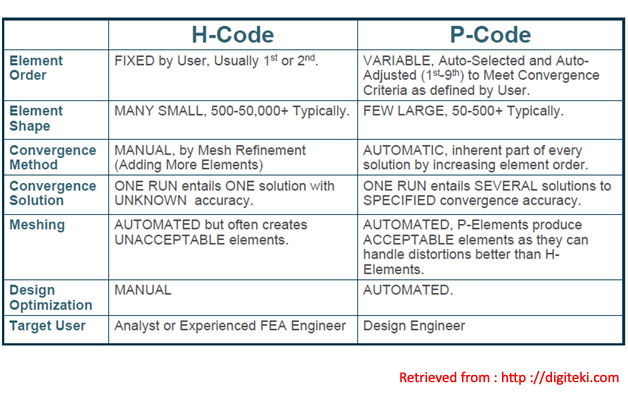
h-method –> The h-method improves results by using a finer mesh of the same type of element. This method refers to decreasing the characteristic length (h) of elements, dividing each existing element into two or more elements without changing the type of elements used.
p-method –> The p-method improves results by using the same mesh but increasing the displacement field accuracy in each element. This method refers to increasing the degree of the highest complete polynomial (p) within an element without changing the number of elements used.
The difference between the two methods lies in how these elements are treated. The h-method uses many simple elements, whereas the p-method uses few complex elements.
H-Method
More accurate information is obtained by increasing the number of elements.The name for the h-method is borrowed from mathematics. The variable h is used to specify the step size in numeric integration. If a part is modeled with a very course mesh, then the stress distribution across the part will be very inaccurate. In order to increase the accuracy of the solution, more elements must be added. This means creating a finer mesh. As an initial run, a course mesh is used to model the problem. A solution is obtained. To check this solution, a finer mesh is created. The mesh must always be changed if a more accurate solution is desired. The problem is run again to obtain a second solution. If there is a large difference between the two solutions, then the mesh must be made even finer and then solve the solution again. This process is repeated until the solution is not changing much from run to run.

P-Method
The p in p-method stands for polynomial. Large elements and complex shape functions are used in p-method problems. In order to increase the accuracy of the solution, the complexity of the shape function must be increased. Increasing the polynomial order increases the complexity of the shape function.The mesh does not need to be changed when using the p-method.
As an initial run, the solution might be solved using a first order polynomial shape function. A solution is obtained. To check the solution the problem will be solved again using a more complicated shape function. For the second run, the solution may be solved using a third order polynomial shape function. A second solution is obtained. The output from the two runs is compared.
If there is a large difference between the two solutions, then the solution should be run using a third order polynomial shape function. This process is repeated until the solution is not changing much from run to run.

References :
Good Solid Modeling, Bad FEA by PAUL KUROWSKI
H-Code vs. P-Code : The Facts (Why Mechanica (Pro/ENGINEER Structural Simulation Option) is a better Solution for Design Engineers).
Thank You…..Everyone is Number One
Mesh Consideration in FEA and CFD Analysis

Meshing is still one of the most important tasks for most CAE users. You need make judgements whether the mesh is good enough for your physical problem. Here are the mesh consideration in FEA and CFD analysis. I know there are probably some other good considerations. If you get one, please post it in the comments box below.
1. For simple comparison of different designs, coarse mesh is OK but for accurate stresses, finer mesh is needed.
2. Invest elements at locations of interest (refining the mesh only in the regions of interest). Greater numbers of elements require more compute resource (memory / processing time). Balance the fidelity of the simulation with available resources.
3. Elements distorted from their basic shape can be less accurate. Greater the distortion, the greater the error. Four types of distortion : Aspect ratio (elongation), Angular distortion (skew and taper), Volumetric distortion, Mid node position distortion (higher order elements)

4. When you choose an element type, you are implicitly choosing and accepting the element shape function assumed for that element type. Therefore, check the shape function information before you choose an element type.
Tegangan Maksimum Pada Pelat Berlubang (Elliptical Hole)


Persamaan untuk menghitung tegangan maksimum diberikan oleh :
![]() , dimana K adalah stress concentration factor
, dimana K adalah stress concentration factor
Persamaan untuk menghitung tegangan (σnom) pada plat (finite plate) dengan lubang yang berbentuk elips diberikan oleh persamaan :